What is OSI Layers In Networking And How Does It Work?
When we start learning computer network science, the first thing we learn is usually TCP / IP. TCP / IP can be analogized like language. When humans exchange information, humans will speak in a language that can be understood by the speaker and listener.
Likewise, the computer or host on a network. In order for communication and information exchange to be well established, the same language is needed. Although the network host brands are different, the host can still communicate with other hosts because it uses the same communication standard, namely TCP / IP.
The internet protocol was first designed in the 1980s. However, in the 1990s where the internet was increasingly popular and there were more and more hosts, protocols began to emerge that could only be used by certain circles, or protocols made by certain manufacturers that were not necessarily compatible with other protocols from other factories as well.
Finally, the International Standards Organization (ISO) body made standardization of the protocol that is currently known as the Open System Interconnection protocol model or abbreviated OSI. The OSI model is a reference and basic concept of the theory of how a protocol works. In its development TCP / IP is used as the de-facto standard.
Table of Contents
OSI Layer
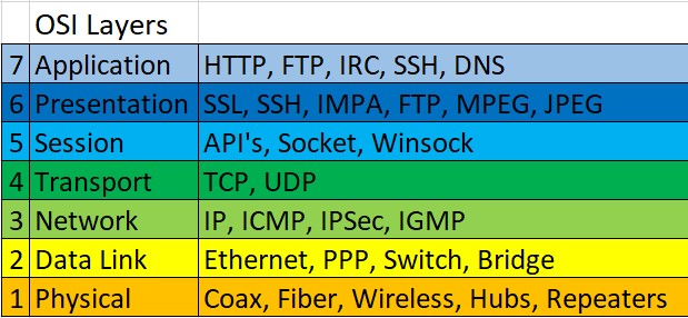
When ISO (International Standards Organization) standardizes the protocol, a standard reference model is created that contains the protocol’s work. The reference model is then called the Open System Interconnection (OSI). Based on the X.200 recommendation document, this OSI standard has 7 layers. Each of these layers has a different function definition.

Layer 7: Application Layer
This is the layer where the end user interface interacts with applications that work using network functionality, regulates how the application works using network resources, to then give a message when an error occurs. Some services and protocols that are at this layer such as HTTP, FTP, SMTP, etc.
Read: How To Find My IP Address?
Layer 6: Presentation Layer
This layer works by translating the data format that the application wishes to transmit over the network, into a format that can be transmitted by the network. At this layer also the data will be encrypted or described.
Layer 5: Session Layer
The session layer will define how connections can be made, maintained, or destroyed. At this layer, there are the Name Recognition, NFS & SMB protocols.
Layer 4: Transport Layer
This layer will do the data breakdown into data packages and provide sequential numbers on the data packages so that they can be rearranged when they reach the destination. In addition, at this layer, will determine the protocol that will be used to transmit data, for example the TCP protocol. This protocol will send data packets, while also ensuring that the packet is received successfully (acknowledgment), and retransmitting packages that are lost or damaged in the middle of the road.
Layer 3: Network Layer
The network layer will create headers for packets that contain IP information, both the IP sending data and the destination IP data. Under certain conditions, this layer will also do routing through internetworking using routers and layer-3 switches
Layer 2: Data-link Layer
The function is to determine how the data bits are grouped into a format called a frame. In addition, at this level error correction, flow control, hardware addressing (such as Media Access Control Address (MAC Address)) occur, and determine how network devices such as hubs, bridges, repeaters, and layer 2 switches operate. The IEEE 802 specification, divides this level into two child levels, namely the Logical Link Control (LLC) layer and the Media Access Control (MAC) layer.
Layer 1: Physical Layer
The Physcal Layer works by defining network transmission media, signaling methods, bit synchronization, network architecture (such as Ethernet or Token Ring), network topology and cabling. In addition, this level also defines how the Network Interface Card (NIC) can interact with cable or radio media.
The process of sending data through each of these layers can be analogous to when we sent a letter. The contents of the letter are the data we will send (layer 7 -> 5). Then according to the shipping standard, we enter the contents of the letter into an envelope (layer – 4). So that our mail can be sent, we need to add the address where the letter will be sent, also who sent the letter (layer – 3). Furthermore, we submit the letter to the expedition, and the expedition will send our letter earlier (layer – 2 & 1).
Read: How To Change IP address
Packet Header
In the previous review we discussed how the process of a data is transmitted, now we will try to unpack a data. What is the contents of all the data so that the data can be transmitted. when we analogize sending data on the internet like sending a POS, we can say the data is the contents of the letter, then the packet header is envelopes, stamps, addresses, and other equipment. This header package provides some additional information. If we examine a data packet that is transmitted using ipv4, we can see the contents of the data package as shown below:
IPVer:
Stores information on the IP version used (IPv4 or IPv6).
IHL (IP Header Leght): Information on the overall length of the data packet header. The minimum IP header length is 20 bits, and the maximum length is 24 bits.
TOS:
Is a field in the IPv4 header that has a length of 8 bits and is used to indicate the type of Quality of Service (QoS) used by the datagram concerned to be delivered to internetwork routers. This TOS implementation is usually when we do HIT limitation on proxy web proxy or VOIP service.
16 Bit Total Length: This 16-bit entry provides information on the size of the entire packet (fragment) including the header and data. Information is displayed in bytes format
16 Bit Identification, Fragment Offset Flag / Length: When the ip packet is running on the internet, this packet may pass through several routers that cannot handle the packet size, for example the Maximum transmission unit (MTU) value is smaller than the IP datagram size, then the packet will be broken or fragmented into smaller packages which will then be rearranged afterwards. This parameter will be used for fragmentation and rearrangement.
TTL:
It is possible that an IP packet is running aimlessly on the Internet network. Examples of cases such as the existence of routing errors or routing loops. To prevent this packet from circling on the internet forever, this TTL value will be reduced every time the data packet passes through the router. When the TTL value of a data packet has expired or has a value of 0, then the packet will be dropped or discarded.
Protocol:
Contains what protocol information is used to transmit data.
16 Bit Header Checksum: the value information is calculated based on the IP header content calculation. Used to determine whether there is an error when transmitting data.
32 Bit Source IP Address: 32 bits of IP packet data source information.
32 Bit Destination IP Address: 32 bits of IP information the data packet is addressed to.
Options (if any):
This parameter is rarely used, has varying lengths, from 0 to multiples of 32 bits. This parameter can be used to store a value for security options, Record Route, Time Stamp, etc.
Data:
It contains data transmitted.
From the packet header information above, data can be sent from one host to another.


